Project overview
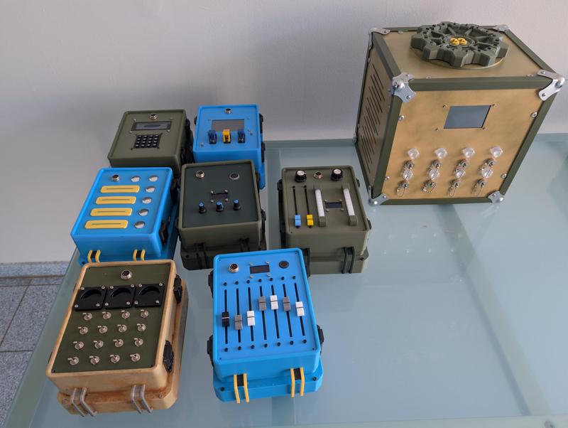
The Fallout Escape Game is a set of seven self-contained electronics puzzle boxes and a central hub whose motorised vault door only opens once every puzzle reports a correct solution. It is a single, non-commercial exhibition piece inspired by the world of Fallout, and it had its first public outing at Maker Faire Hannover 2026.
Each puzzle is deliberately built around a different electronic principle: a matrix keypad with a dedicated scanner chip, linear faders read through a 12-bit ADC, a barcode scanner that identifies sample vials, a switch matrix on a port expander, and a TCS34725 colour sensor that recognises anodised aluminium keycards by their finish. The point is not the puzzle alone but what the puzzle exposes — players see how microcontrollers, sensors and actuators work together, because every box makes its own input method visible.
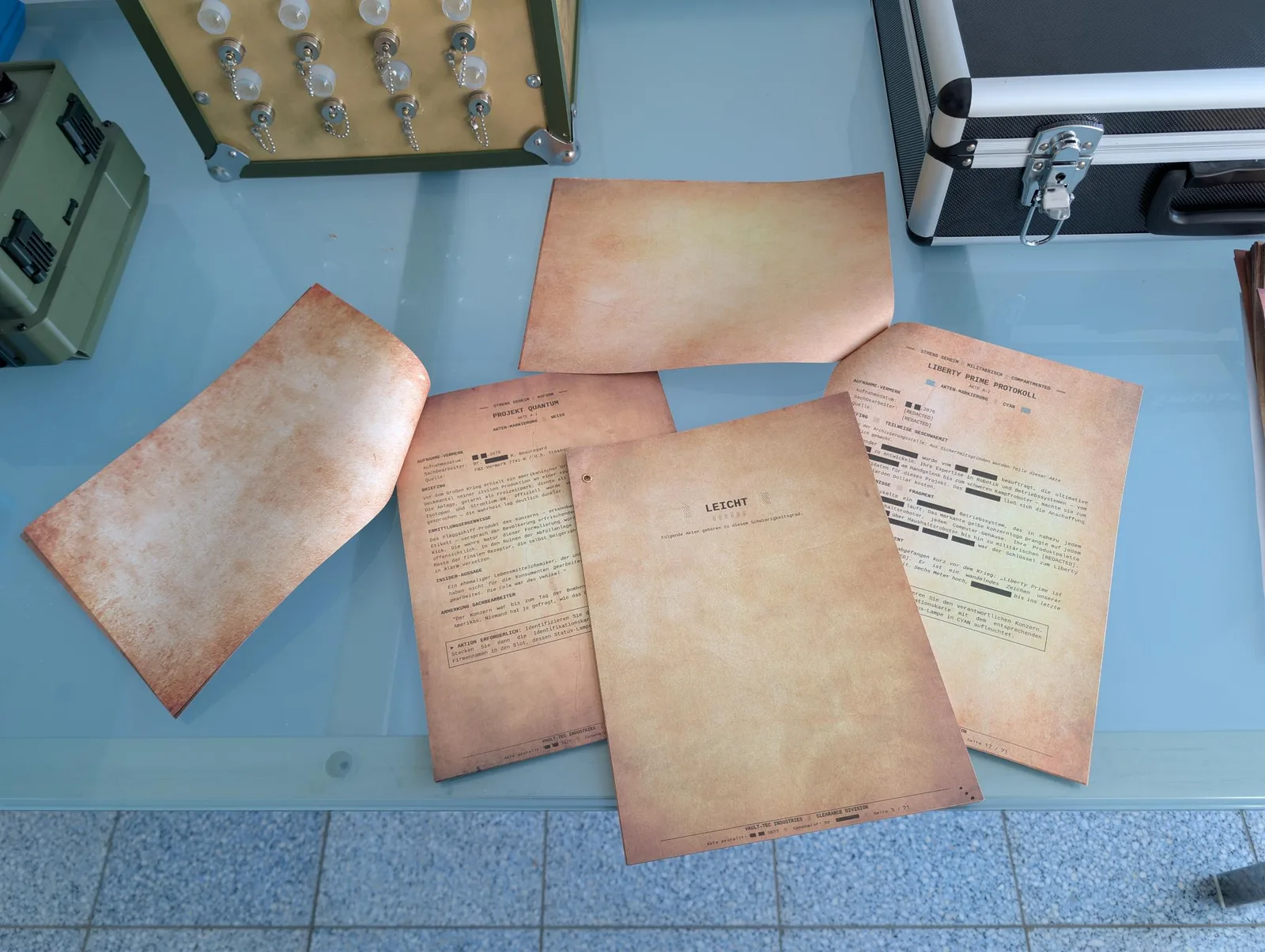
The game is designed for one to two players and remains workable for up to three. Solutions cannot be brute-forced: the printed player aids have to be read and cross-referenced, and those aids exist in three graded difficulty levels, so the same hardware serves beginners and experienced players without changes to the boxes. The puzzle texts themselves are written in German and follow the flavour and fluff of the source material.
Not every box is a puzzle in the usual sense. The Trolly module checks whether the player actually read the documentation. Anyone who skipped it is forced into a decision: reach the goal by letting fictional people die, or go back and read. It is the trolley problem from moral philosophy, wired into a prop.
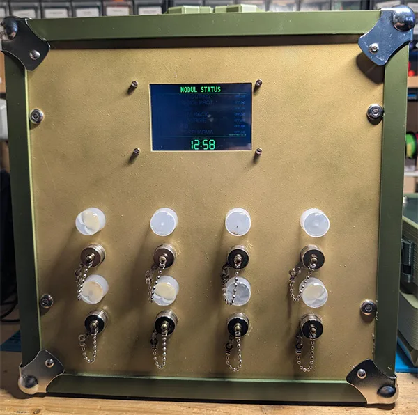
All boxes plug into the gameHub, a weathered olive console with a valve wheel on top, a status display listing the state of each module, and eight connector ports on the front panel. A separate Gamemaster console, built on an off-the-shelf Waveshare ESP32-S3 Touch AMOLED 2.41, controls the run: it sets the timer, the difficulty level and the volume, shows the status of every module, and can mark an individual puzzle as solved when a group gets stuck. When the last puzzle is solved, the VaultLift module raises the vault door.
Everything created for this project — firmware, PCB design files, STL files and the printed documents — is published under the PolyForm Noncommercial License. The project has no commercial background whatsoever and is not for sale; it is a one-off that anyone is free to rebuild for their own non-commercial use. All names, logos and trademarks from the Fallout universe remain the property of Bethesda Softworks and are used here only as fan-made set dressing. Those elements are not covered by the project licence and are not offered for download.
Electronics and control
Every module board shares the same front end: an ESP32-S3-DevKitC-1, a 1000 µF and 22 µF input buffer, an SMD1812P110TF resettable PPTC fuse, a TPAP2112K-3.3 LDO for the 3.3 V rail, and a JST-XH 8-pin connector to the hub. Only the module-specific section differs, which keeps board bring-up and fault-finding identical across the whole set. Several modules share an identical board revision, the Color Scanner runs on a recycled board from an earlier project, and the Gamemaster console uses a Waveshare development board as delivered.
| Module | Function | Key part |
|---|---|---|
| gameHub | Game state, status display, sound, eight module ports | MCP23017, 24LC512, DFPlayer Mini |
| VaultLift | Raises the vault door on the hub | TMC2209 with NEMA 17 |
| RobCo Hack | Keypad terminal | TCA8418 keyboard scanner |
| Profiler | Seven linear faders read as analogue values, one per S.P.E.C.I.A.L. attribute | MCP3208 12-bit SPI ADC |
| FEVLab | Scans the FEV sample vials | Barcode scanner with OLED |
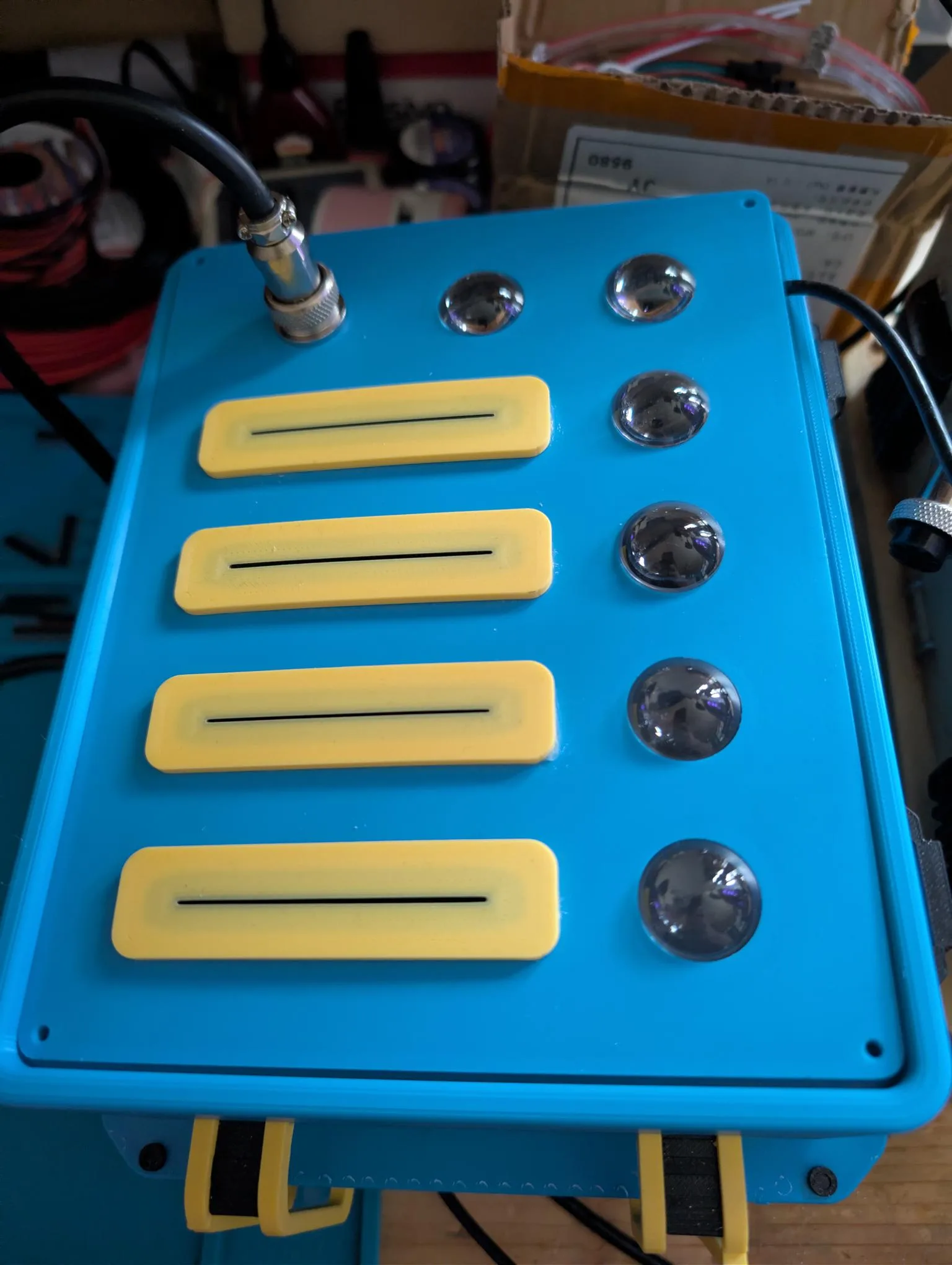
| MedTekPharma | Two linear faders, two LED strips and an OLED readout | MCP23017 |
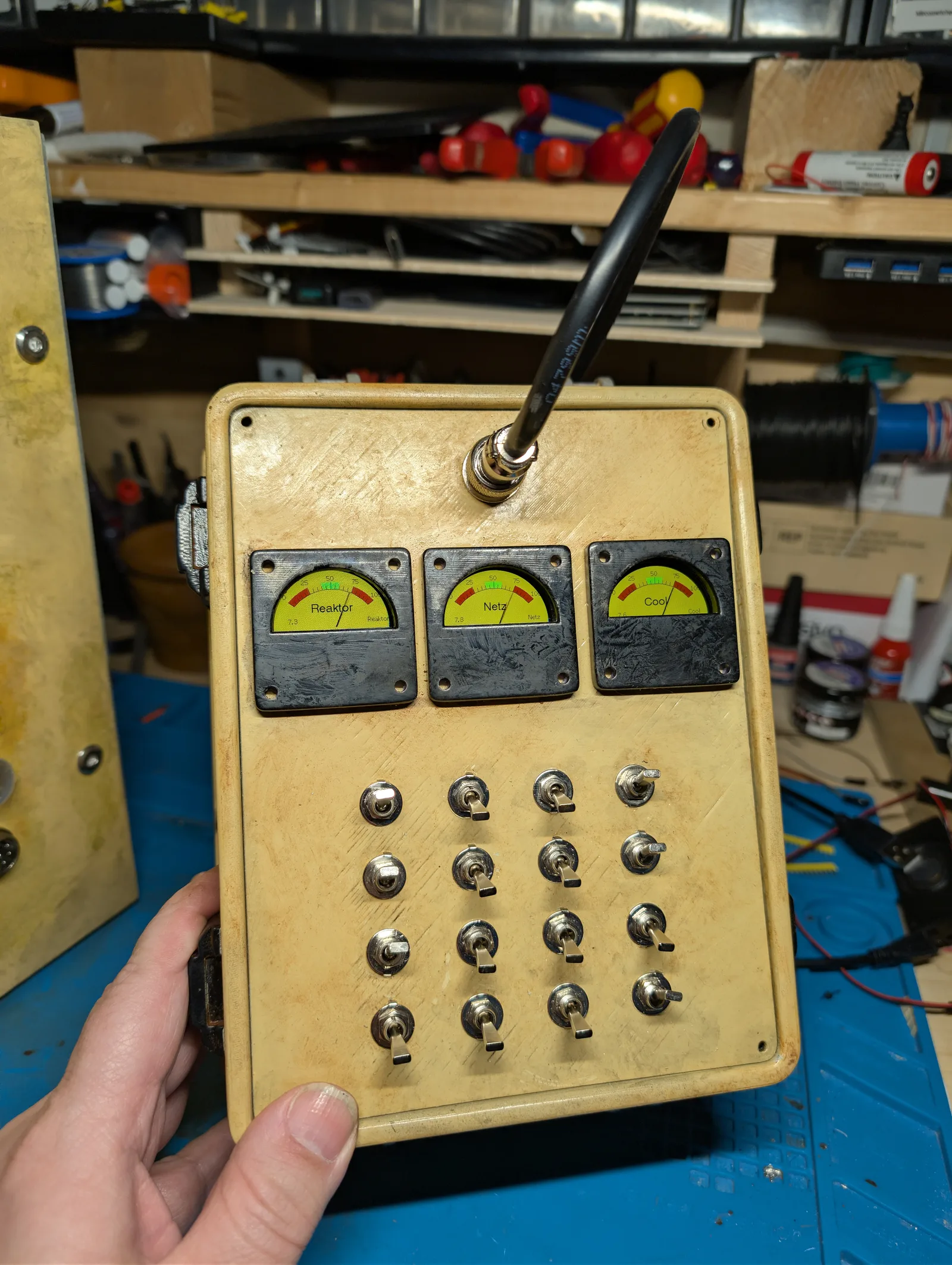
| RePower | Sixteen toggle switches and three simulated meters | 3 x GC9A01 round LCD |
| Color Scanner | Four card slots identifying keycards by their anodised colour | TCS34725 RGB sensor |
| Trolly | Checks whether the documentation was actually read | — |
| Gamemaster | Run control: timer, difficulty, volume, module status, manual solve override | Waveshare ESP32-S3 Touch AMOLED 2.41 |
The 8-pin cable carries no data. It supplies 12 V, 5 V, GND and a presence signal that tells the hub which ports are occupied. All communication between the modules and the hub runs over ESP-NOW with a custom encryption layer, so adding a module means plugging in one cable rather than routing a bus.
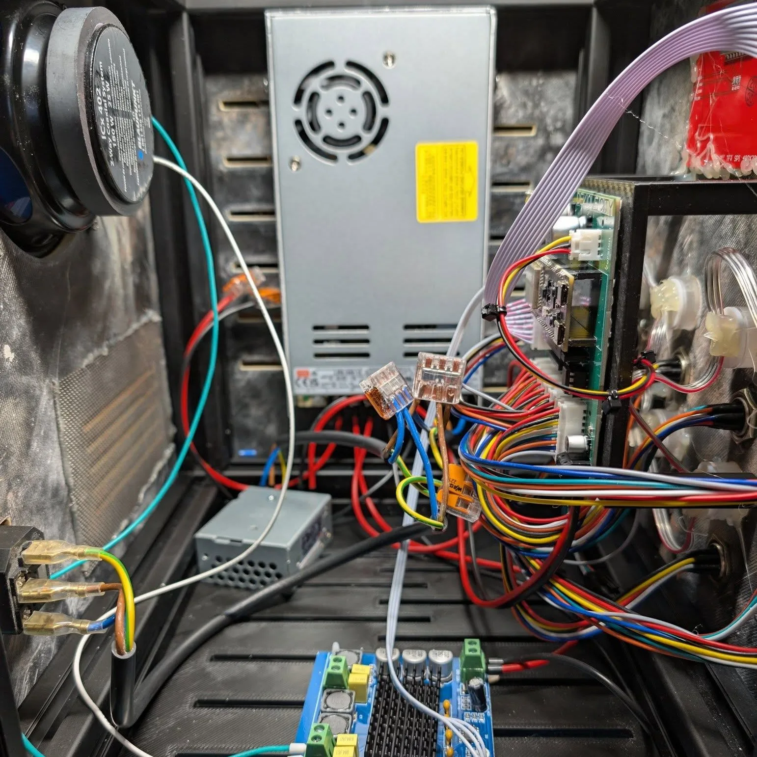
Power comes from two separate switch-mode supplies: 400 W at 5 V for all logic, displays and sensors, and 600 W at 12 V for the 300 W class-D amplifier and the NEMA 17. Both are deliberately oversized so that further modules can be added without touching the power design. Step-down converters were used in earlier revisions and dropped entirely — the combined current draw made dedicated supplies the simpler answer.
The hub board carries an ESP32-S3-DevKitC-1U-N8R8, an MCP23017 port expander for the eight module ports, a 24LC512 EEPROM for persistent settings and the high score, a DFPlayer Mini feeding the amplifier and a two-way coaxial loudspeaker, a WS2812B output, and an SPI display for the module status screen. Eight dome-shaped indicator LEDs sit above the eight connectors on the front panel, one per port, so the state of every connected module is readable from the hub itself. The same LED type is reused on the Color Scanner.
Mechanical construction
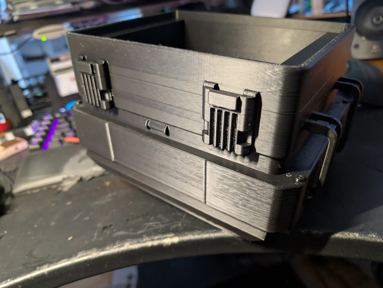
The puzzle enclosures and the hub lift mechanism were developed to specification for this project and bought in; all rights to both remain with Devious City. Every other part — front panels, fader caps, bezels, mounts, connector plates — was designed in FreeCAD and printed in-house across three machines, split by what each part has to do. Structural and panel parts run in PETG from Extrudr on a Bambu Lab H2C. Everything where surface finish or optical clarity decides the result goes to resin on an Anycubic M7 Pro or Anycubic Photon P1: the fader caps, the transparent tubes that act as light guides over the WS2812B LEDs, the various knob and port caps, and decorative parts such as the black surrounds of the meters.
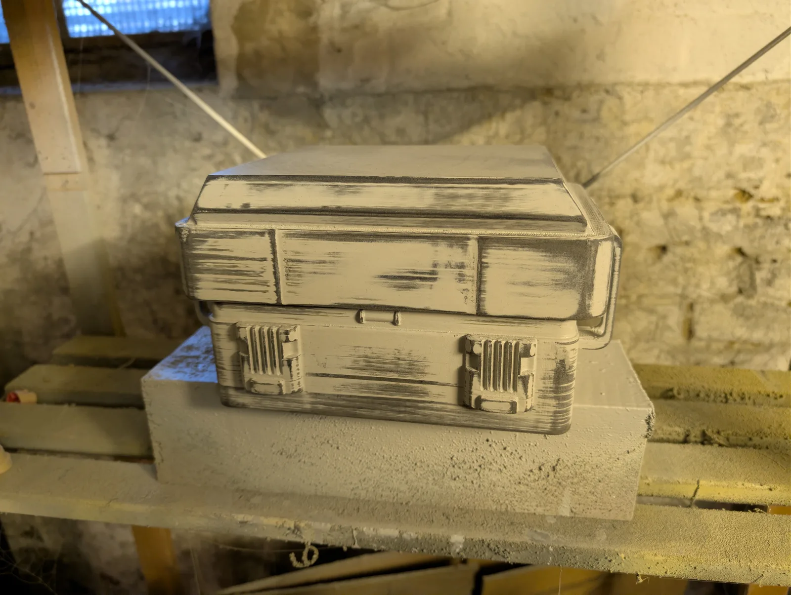
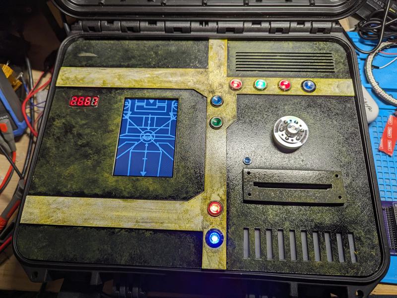
Two finishing routes are used. Some parts are printed directly in the final colour and need no paint at all; others are sprayed and then weathered with pigments, applied with brushing and drybrushing techniques to build up the scavenged look along edges and panel lines. Colours vary by module: olive, light blue with yellow accents, dark grey and bone all appear in the finished set.
The three meters on the RePower module are not moving-coil instruments. They are GC9A01 round LCDs sitting behind resin-printed bezels, which keeps the needle behaviour fully under software control while preserving the analogue appearance.
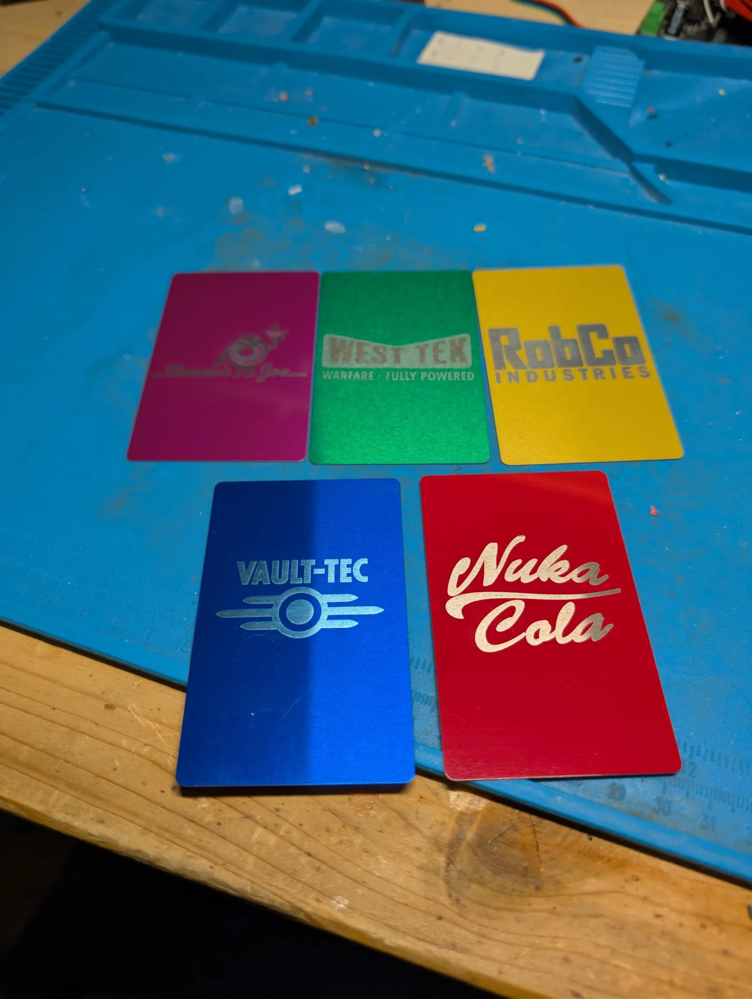
The keycards are anodised aluminium blanks, engraved in-house with the laser module of the same H2C that prints the filament parts — the H-series modular toolhead swaps the print head for the laser, so engraving and printing happen on one machine. Anodised aluminium was chosen because the engraving exposes the bare metal underneath, giving high-contrast markings without any printed layer that could wear off in play. There are five cards but only four slots on the Color Scanner: one card is a deliberate red herring, and nothing on the module hints at which one.
The player aids need no artificial ageing: the paper was bought pre-aged and simply run through a printer, which avoids the warping and ink bleed that comes from staining sheets after printing.
Software
Development happens in PlatformIO; the sources are converted for the Arduino IDE so that they stay accessible to anyone rebuilding a single module. Each module has its own repository rather than living in a monorepo, which means a rebuilder only needs the code for the box they are actually building.
Module-to-hub traffic uses ESP-NOW wrapped in a custom encryption layer. The hub holds the game state, drives the status display and the soundscape, and writes persistent settings and the high score to the 24LC512 EEPROM so that both survive a power cycle.
Lessons learned
A matrix keypad on plain GPIOs is not worth the effort. Scanning the keypad directly from the ESP32-S3 caused persistent problems, contact bounce among them. Switching to a TCA8418 keyboard controller, which handles scanning and debouncing in hardware, removed the entire class of issues in one step. Behind the level translator it is a two-wire I2C part, so it costs almost no board area.
Colour-based card readers need a light-tight slot. The first version gave inconsistent results because stray ambient light and the colour of the printing on the card both skewed the measurement. The card slot had to be built very tightly around the card so that only the sensor’s own illumination reaches the surface being measured.
A single-sided drive jams a printed lift. The first vault door mechanism had the stepper on one side and a guide rail on the other. The torque step at stepper start-up tilted the platform and it bound repeatedly. It only ran reliably after moving to two guide rods with the lead screw in the centre of the platform, so the drive force acts through the centre of mass instead of against one edge.
Every module needs its own fuse. Because modules are plugged into the hub while it is running, the inrush produces current spikes on the shared rails. Early boards were destroyed learning this. A resettable PPTC fuse on each module input catches the spike locally and costs one part per board.