Project overview
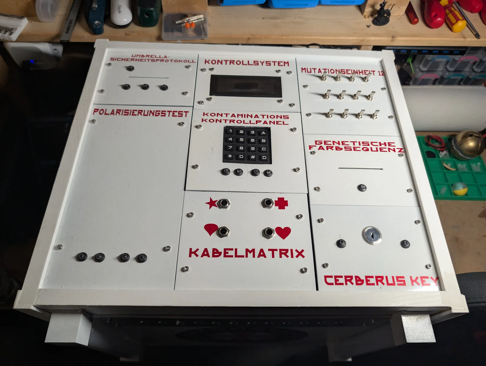
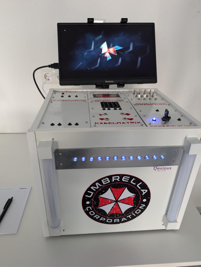
The Resident Evil Escape Game packs a complete escape room into a single white case. One or two players have fifteen minutes to neutralise the virus, working through a chain of puzzles spread across the panels on the lid — a polarisation test, a contamination control panel, a cable matrix, a genetic colour sequence, a mutation panel and a security protocol, ending at the key switch.
Behind those panels sit twelve independent modules. Each runs its own ESP32 with a fixed address on the game network and talks to a Raspberry Pi acting as MQTT broker. Nothing is wired module to module, which is what allows a game to be set up, torn down and transported as one object rather than a room.
The game has run at two company events and at Maker Faire Hannover 2025, and a revised version goes to Maker Faire 2026.
Everything created for this project — firmware, board designs and the printed parts — is published under the PolyForm Noncommercial License. The project has no commercial background and is not for sale. Resident Evil, the Umbrella Corporation and all associated names and logos are the property of Capcom; this is a fan-made exhibition piece and none of those elements are covered by the project licence.
Electronics and control
Every module is the same idea repeated: an ESP32 with a fixed IP, subscribed to
its own command topic under umbrella/, plus the shared umbrella/ping. Three
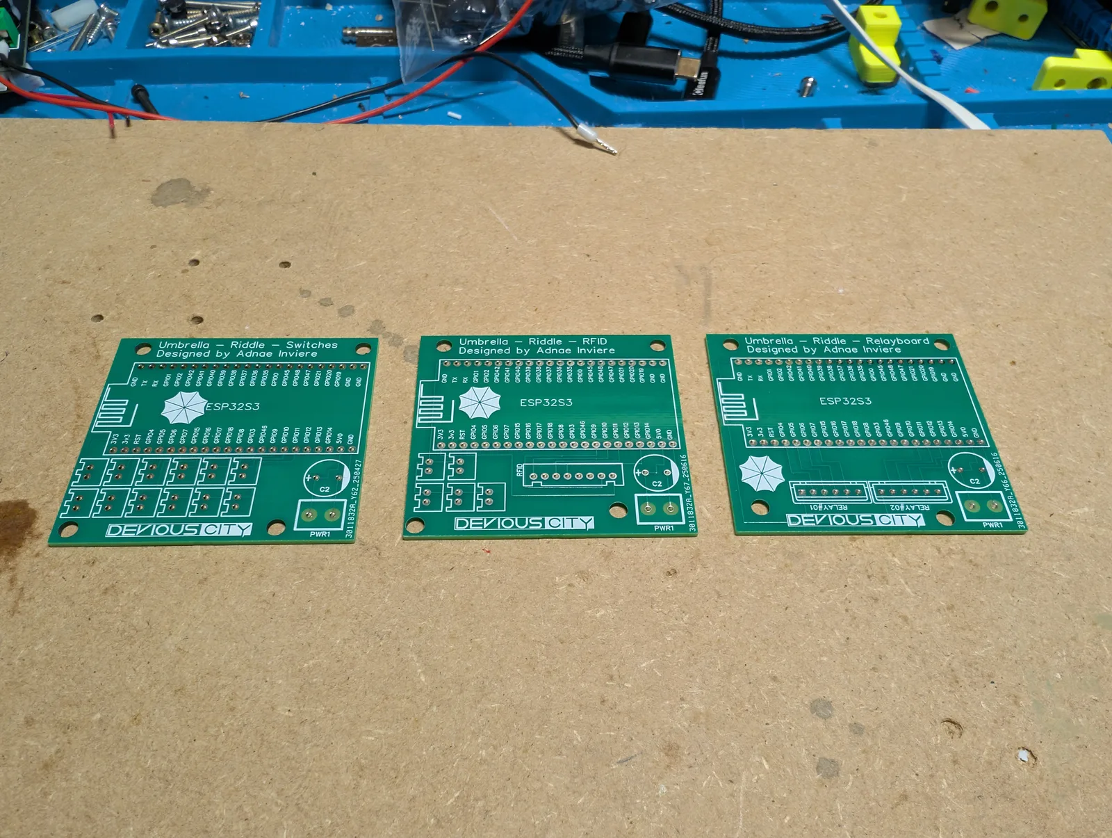
of the boards were designed specifically for this build — a switch carrier, an
RFID carrier and a relay carrier — all sharing one ESP32-S3 footprint so the
bring-up procedure is identical across them.
| Panel | Module | Address | Key part |
|---|---|---|---|
| Polarisationstest | Magnet Riddle | .17 | — |
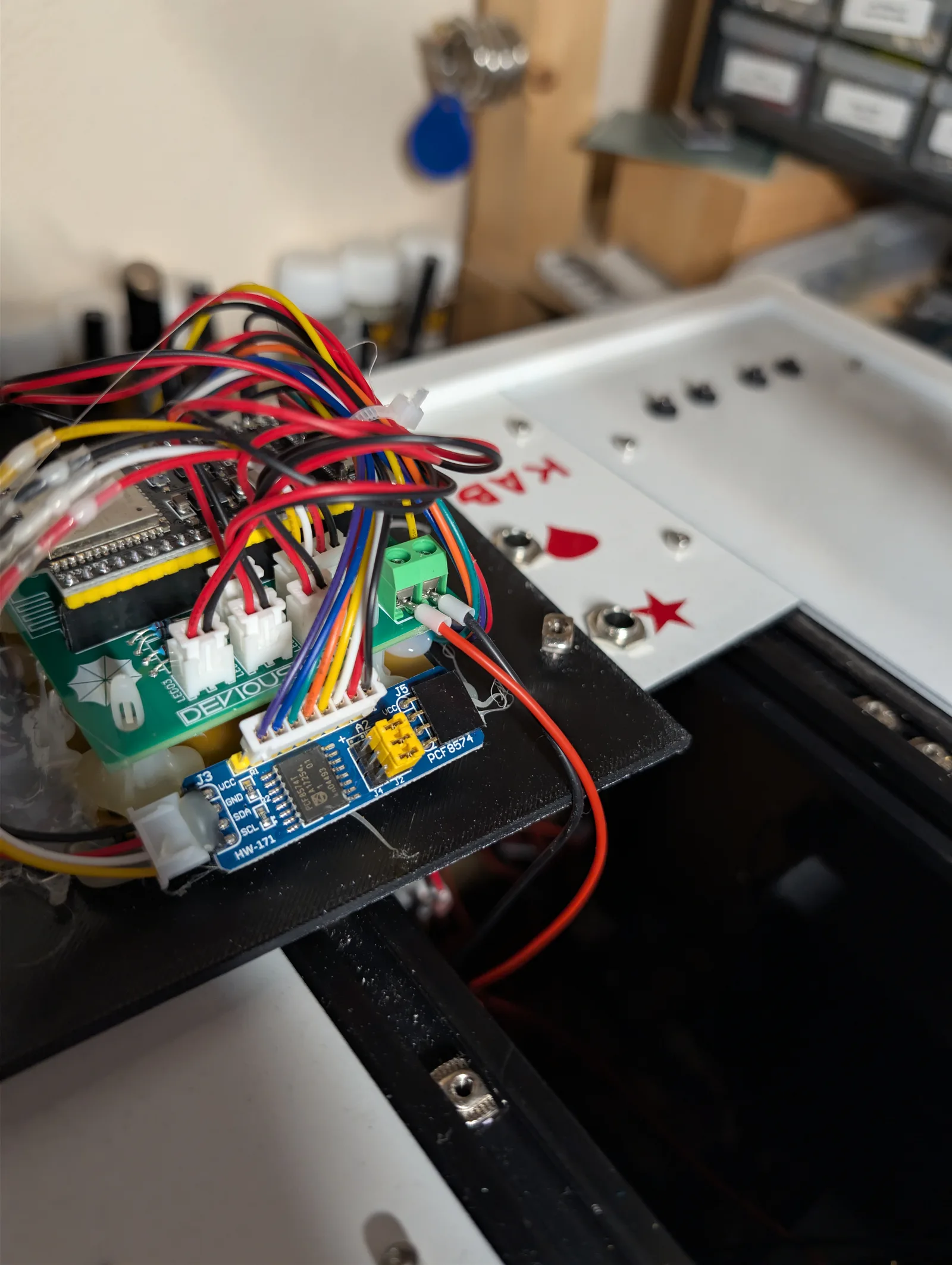
| Kontaminations-Kontrollpanel | Keypad | .14 | PCF8574 at 0x20 |
| Kabelmatrix | Bridged Riddle | .15 | — |
| Genetische Farbsequenz | Colour Riddle | .11 | MFRC522 |
| Mutationspanel | Switch Riddle | .10 | — |
| Sicherheitsprotokoll | RFID Reader | .16 | MFRC522 |
| Final key switch | Cerberus | .12 | — |
| — | LCD Display | .13 | LCD 20 x 4 at 0x27 |
| — | Status LEDs, twelve front indicators | .18 | — |
| — | Relay Board | .19 | — |
| — | Gimmick Board, the two front tubes | .20 | 2 x 48 WS2812B, FastLED |
| — | Game Master Console | — | Waveshare ESP32-S3 Touch AMOLED 2.41 |
Power for the whole installation comes from an ATX PC supply. With twelve controllers, two LED tubes, four electronic locks and a Raspberry Pi in one enclosure, the separate 12 V, 5 V and 3.3 V rails and the current available on each are worth more than the space a purpose-built supply would have saved.
Audio does not come out of the modules at all. The Raspberry Pi output runs through an HDMI splitter that separates picture from sound: the picture goes to the monitor above the case, the sound goes to an amplifier and a speaker at the rear. Keeping the soundtrack on the media player rather than on a module means video and audio can never drift apart.
Two modules own shared state rather than just reporting their own. Cerberus
publishes the active puzzle variant as a retained message on
umbrella/riddle/master, and the LCD module owns the countdown and publishes it
retained on umbrella/timer/state. Any module that reboots picks both up from
the broker on reconnect instead of waiting for the next broadcast.
The two translucent tubes flanking the front are driven by the gimmick board and visualise the virus and the antivirus as the game progresses. They were originally meant to hang off the status LED module together with the front indicators; the power supply would not carry both, so the tubes moved to a board of their own. The unused path is still present in the status module.
The twelve indicator LEDs on the front of the case serve two different purposes depending on when you look at them. Before a run they are a readiness display — they confirm that every module is online, which is the check that matters when the case has just been carried into a hall and switched on. During the game the same row shows how far the players have got.
Mechanical construction
All panels are 3D printed in Qidi ASA on a Qidi X-Max 3, and that is a deliberate choice rather than a compromise. Drawing a row of evenly spaced holes in CAD and letting the printer place them is more reliable than marking and drilling them by hand, and the panels are full of switch, socket and display cutouts that all have to line up with each other. ASA also takes the handling a public installation gets better than PLA would.
The printed panels are sprayed in gloss white and the lettering is cut vinyl applied over the paint.
The case is a white cube with aluminium corner profiles, translucent tubes at the front corners and a metal strip carrying the indicator LEDs. A monitor mounts above the lid for the player-facing display.
The rear of the case carries the service connections: an HDMI socket and a USB socket for the monitor, and an RJ45 socket wired straight to the Raspberry Pi. That last one matters more than it looks — it means the broker and the media player can be reached with a laptop and a patch cable at an event, without opening a case that has twelve modules wired into it.
Software
Each module runs Arduino firmware on the ESP32 with PubSubClient for MQTT and
Arduino_JSON for the command payloads. Commands arrive as JSON on a per-module
topic, so the same message format works for a keypad, a relay board and a
display without a shared protocol layer.
The GitLab repository has a CI/CD stage that scrambles the puzzle solutions on the way into the published version. That is what makes it possible to open the source at all: the architecture, the MQTT structure and the module firmware are readable, while the answers a player would need are not the ones in the public tree.
Larger buffers are allocated in PSRAM rather than on the heap, and the modules run a custom partition table with a single large application partition.
The Raspberry Pi runs a Python daemon that is broker, media player and watchdog
at once. It loops an idle video on the monitor until a game starts, then plays a
briefing chosen by the active puzzle variant, followed by a clip for each phase
and for each of the two bad endings. Volume is a game master command and is
written to disk atomically — temporary file, fsync, then rename — so a power
cut cannot leave a corrupt setting behind. A separate thread pings every ten
seconds and marks any module that has been silent for thirty seconds as offline,
which is what feeds the readiness display on the front.
Lessons learned
Retained messages are what make a twelve-node game survivable. A module that loses power or crashes mid-run has to come back knowing which puzzle variant is active and how much time is left. Publishing both as retained MQTT messages means recovery is automatic and silent — the alternative is a module that rejoins in the wrong state, which on a show floor is indistinguishable from a broken puzzle.
Check the power budget before assigning peripherals to a module. The two front tubes and the twelve indicators were meant to share one controller. The supply could not carry both, and the fix was not a bigger regulator but a second board with its own feed. Splitting by current draw rather than by logical grouping is the lesson; the abandoned path is still visible in the firmware.
Design for the room, not the workshop. A game master command exists purely to replay the briefing, because at a trade fair the audio is simply lost to the noise around the stand and players miss what they were told. It is not a feature anyone specifies at the design stage — it comes from watching a group stand there having heard nothing.
Open source and a puzzle game are not automatically compatible. Publishing the firmware means publishing the answers unless something is done about it. Handling that in CI/CD rather than by keeping two branches by hand means the public repository cannot drift out of sync with the working one, and there is no manual step to forget before a push.