Project overview
The Four-Channel Magnetic Lock is a controller for four electromagnetic holding points with a countdown timer and an MQTT interface. Each channel consists of a magnet in a printed housing and a steel anchor plate with an eye bolt; energising the magnet holds the plate, cutting the current releases it.
It was built as a module for a larger training system that has been in development since 2022 and has not been published. The work is a collaboration with an international manufacturer of BDSM equipment, who is not named here. The countdown is the part that makes it more than a switch: the module gives a set time for all points to be connected, watches the presence contacts, and reports back over MQTT whether that happened. Because the holding is purely electrical, the same module works for remote operation and for unattended use, where no second person is present to open anything by hand.
This page documents a prototype. The hardware is built and working; the failure handling in the firmware is still open work, and the module is not in regular use. Nothing about it is published — no board files, no firmware, no printed parts — and it is not for sale.
Electronics and control
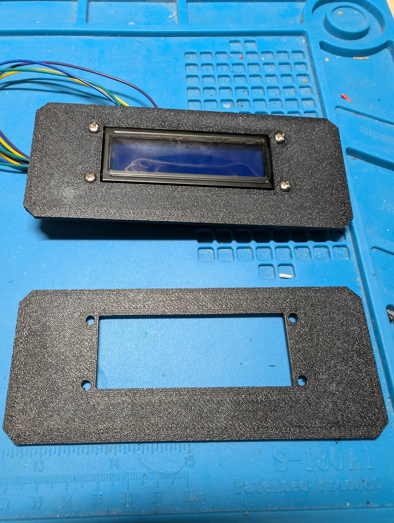
An ESP32-S3 runs the module, with a Waveshare LCD1602 RGB as the status display. The backlight colour carries the state, so the condition of the module is readable across a room without reading the text.
Each channel leaves the enclosure through one six-pin circular connector carrying six lines: 12 V and GND for the magnet, 5 V and GND for the sensing, and two separate presence signals. The two presence lines are the part worth explaining, because they answer different questions:
| Signal | Question it answers |
|---|---|
| Plug present | Is a magnet unit connected to this channel at all? |
| Contact closed | Is the anchor plate seated on that magnet? |
A channel with nothing plugged in is a different state from a channel that is plugged in but open, and the module needs to tell them apart before it starts a countdown against a point that does not exist.
Switching is done by one Heschen JQC-3F(T73) relay per channel between the supply and the magnet. The supply itself sits outside the enclosure and comes in through its own connector, so the only thing inside the housing is low voltage and the switched 12 V.
The release path is deliberately passive. The magnets hold only while current flows, so interrupting the supply — pulling the inlet, switching off the external supply, a power cut — drops all four channels at once with no software involved.
Mechanical construction
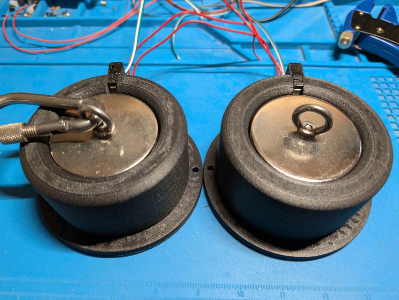
The magnet housings and the panels are printed in PA12-CF on a Qidi X-Max 3. The material was chosen for one reason: an electromagnet energised for an extended period inside a closed housing gets hot, and a housing that softens around a magnet under load is not an acceptable failure. PA12-CF holds its shape at temperatures where the more convenient materials do not.
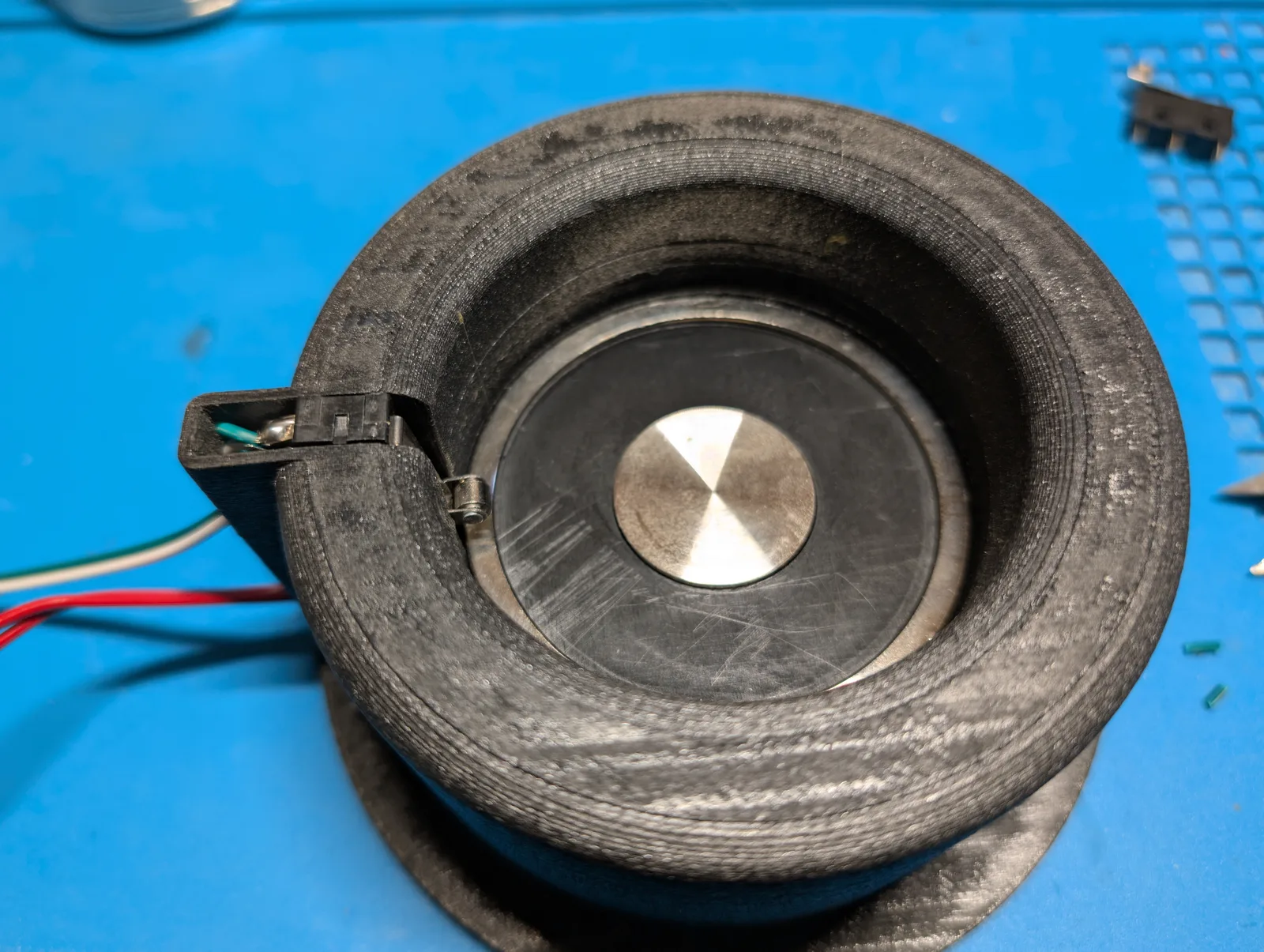
Each housing takes the magnet with its face flush at the opening, a cable channel through the wall, and a lever switch at the rim positioned so that a seated anchor plate closes it.
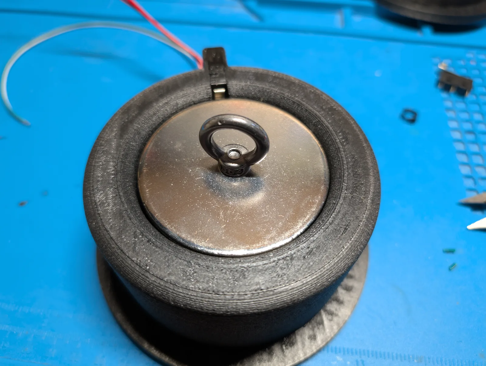
The anchor itself is a short stack rather than a single part. On top sits the steel disc that meets the magnet face; below it a thick rubber layer, and only then the washers and the eye bolt that everything else clips to. The rubber is there as a thermal break. Steel conducts, the magnet runs warm, and without that layer the heat would travel straight through the plate into the attachment point and from there to whoever is on the other end of the carabiner.
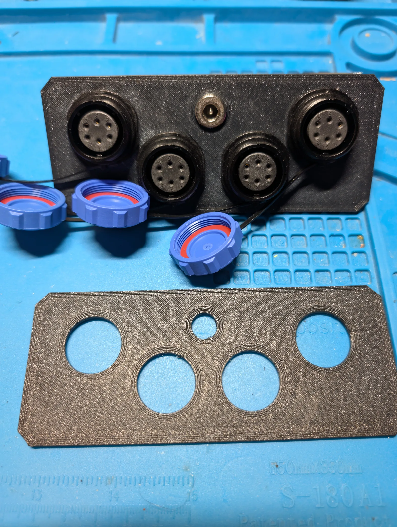
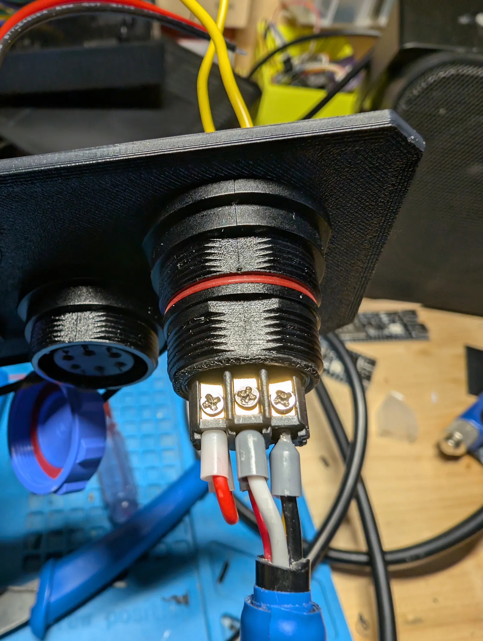
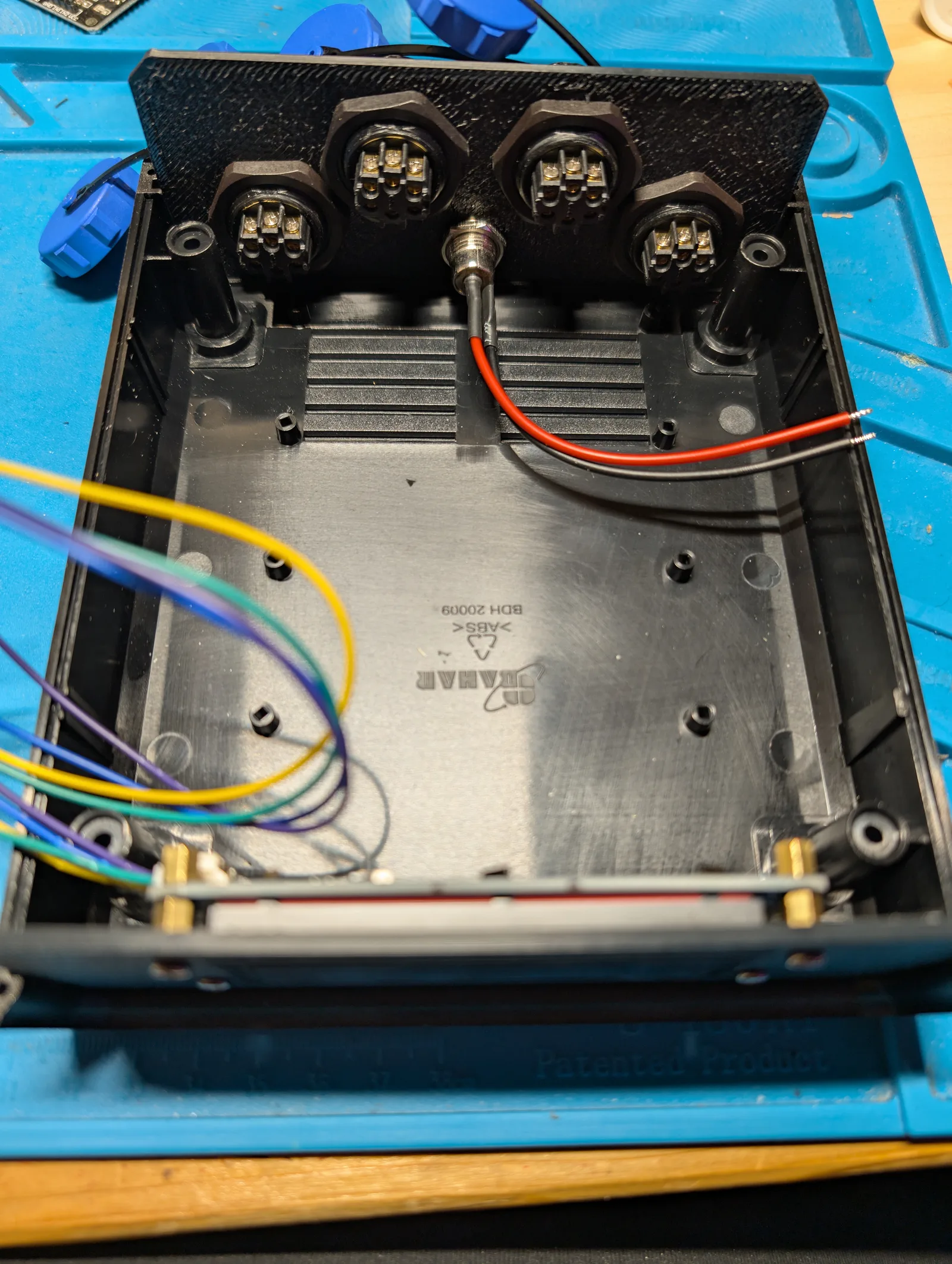
The control enclosure carries all five connectors on one end panel, with screw caps on the unused channels.
Software
The module subscribes per device UUID and reports its state back on its own topics, including a periodic ping so the controlling system can see that it is alive. Commands set the timer and arm the channels; the module answers with the presence state of each point and with a release confirmation when the countdown reaches zero.
The countdown drives the display directly and, at zero, sets the relays back to the released state.
Lessons learned
Size the magnets for the worst case, not the expected load. Each channel uses an 1800 N magnet, far more than any single attachment point needs to carry. That is intentional. A magnet chosen to just about hold will let go under a sudden hard pull, and something that releases unpredictably under load is more dangerous than something that holds reliably. Overspecifying the holding force means the release happens when the controller decides it does, not when the mechanics give up.
Heat leaves an energised coil by more than one path, and each needs its own answer. The obvious one is the housing: sealed around the magnet, warm for as long as the channel is held, which rules out most of the convenient print materials and led to PA12-CF. The less obvious one runs the other way, through the steel anchor plate and into whatever is attached to it. A rubber layer in the anchor stack breaks that path. Solving only the first would have produced a housing that survives perfectly while conducting the problem straight to the person.